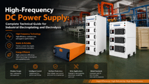
Working Principle: Why is HF Switching Power Supply More Efficient?
Limitations of SCR Rectifiers
Traditional SCR rectifiers regulate output voltage by controlling the conduction angle of each AC cycle. Taking a 50Hz frequency as an example, the minimum adjustment step for output voltage is approximately 3.6°, resulting in:
-
Limited regulation precision
-
Higher harmonic content
-
Bulky transformers (requiring low-frequency magnetic cores)
The Breakthrough of High-Frequency Switching
HF switching power supplies first rectify industrial AC into DC, then perform High-Frequency PWM Modulation via IGBT/MOSFETs: Input (50Hz) → Rectification → Filtering → HF Inversion (20-50kHz) → HF Transformer → Rectified Output
By increasing the switching frequency to 20-50kHz, transformer volume can be reduced by 70-80%, while achieving:
-
Higher power density (kW/kg)
-
Faster dynamic response
-
More precise current and voltage control
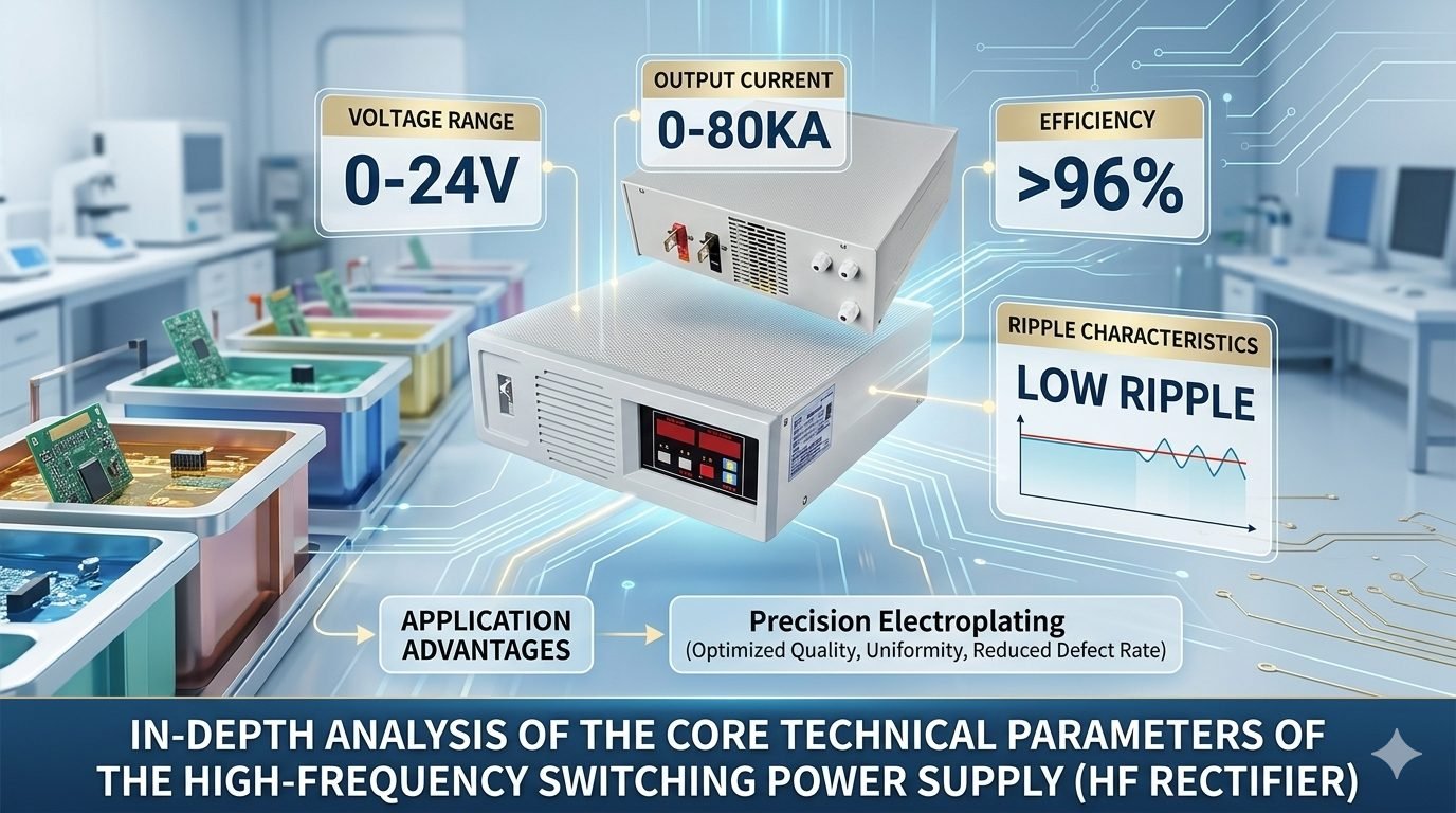
Core Parameter Analysis
Parameter 1: Voltage Range 0-24V
Why is 24V chosen as the upper limit for precision electroplating?
24V covers over 90% of precision electroplating process requirements while maintaining a safe voltage level for the equipment. Voltage Regulation Precision: High-quality HF switching power supplies can achieve a precision of ±0.1V, meeting the requirements of precision craftsmanship.
Parameter 2: Current Range 0-80KA
What does a single 80KA unit signify?
-
It can satisfy the full-load plating area of approximately 80dm² for a medium-sized plating line (1000A/dm² specification).
-
For standard PCB copper plating lines (typically requiring 2000-5000A), it allows for a 1-active, 2-standby configuration.
Parallel Expansion Scheme: When a single 80KA unit is insufficient, multiple units can be connected in parallel: Total Current = N × Single Unit Current × Parallel Coefficient (typically 0.85-0.95) For example, four 80KA units in parallel provide an actual usable current of approximately 280-300KA.
Parameter 3: Efficiency >96%
Why is efficiency so critical? Using a 100kW rectifier as an example:
The efficiency advantage of HF power supplies stems from:
-
Power semiconductors with low conduction loss
-
Low copper loss in HF transformers
-
Soft-switching technology to reduce switching losses
Parameter 4: Ripple Coefficient <3%
The Relationship Between Ripple and Coating Quality Ripple is the AC component superimposed on the DC output. High ripple can lead to:
Note: HF power supply ripple is typically <3%, and can reach <1% when paired with output filter capacitors.
HF Switching Power Supply vs. SCR Rectifier: Application Scenarios
HF Power Supply Advantages
-
Precision Electronic Plating: PCB copper, gold, and wafer plating
-
Space-Constrained Locations: Requirement for compact equipment
-
Fast Parameter Switching: Multi-variety, small-batch production
-
Energy Efficiency: Sensitive to long-term operating costs
SCR Rectifier Advantages
-
Ultra-High Current: Applications where single units exceed 10KA
-
Extremely Low Ripple: Precious metal plating
-
Harsh Environments: High temperature, high humidity, and high dust
-
Simple & Reliable: Sites with limited maintenance capabilities
Selection Advice: Do You Need an HF Power Supply?
Decision Matrix
Answer the following questions:
-
Is the single-tank current requirement <80KA?
-
Do you need to adjust current rapidly (e.g., several times per second)?
-
Is installation space limited?
-
Does the process require ripple <3%?
If you answered “Yes” to 3 or more, an HF switching power supply is recommended.
Typical Case Study: PCB Copper Line in Shenzhen
-
Requirement: 5000A/12V (Double-sided copper plating)
-
Space: Original SCR rectifier occupied 8m²; new line required 3m²
-
Process: High-end HDI boards requiring high coating uniformity
-
Solution: 2 units of QEEHUA HF-5000A/24V (1 active, 1 standby)
-
Result: Equipment volume reduced by 60%, ripple <2%, and annual electricity savings of approx. 80,000 RMB.
Use and Maintenance
Daily Maintenance
-
Ensure unobstructed vents; keep ambient temperature <45℃.
-
Regularly clean dust from fans and heat sinks.
-
Check cooling water quality (if using water-cooled configurations).
Troubleshooting
FAQ
Q: Will HF power supplies interfere with precision testing equipment? A: Modern HF power supplies feature built-in EMI filters and comply with EN 55011 standards. Additional shielding can be added if necessary.
Q: Is the lifespan of an HF power supply shorter than an SCR? A: It depends on the environment. Under normal conditions, power semiconductors can last 10+ years; the main cause of failure is early damage due to poor heat dissipation.
Q: What temperature will a 24V/80KA unit reach at full load? A: This depends on the cooling method. Air-cooled units in a 45℃ environment see a temperature rise of 20-30℃; water-cooled solutions can keep core temperatures below 60℃.
Q: Can one 80KA HF unit power two plating tanks? A: Not recommended. Current distribution accuracy will drop, affecting process stability. It is advised to configure an independent power supply for each tank.