7 Critical Design Rules for Parallel Rectifier Operation & N+1 Redundancy: Avoid Costly Downtime (2026 Guide)
QEEHUA Industrial Rectifier — Applied in Global Industrial Projects
/div>
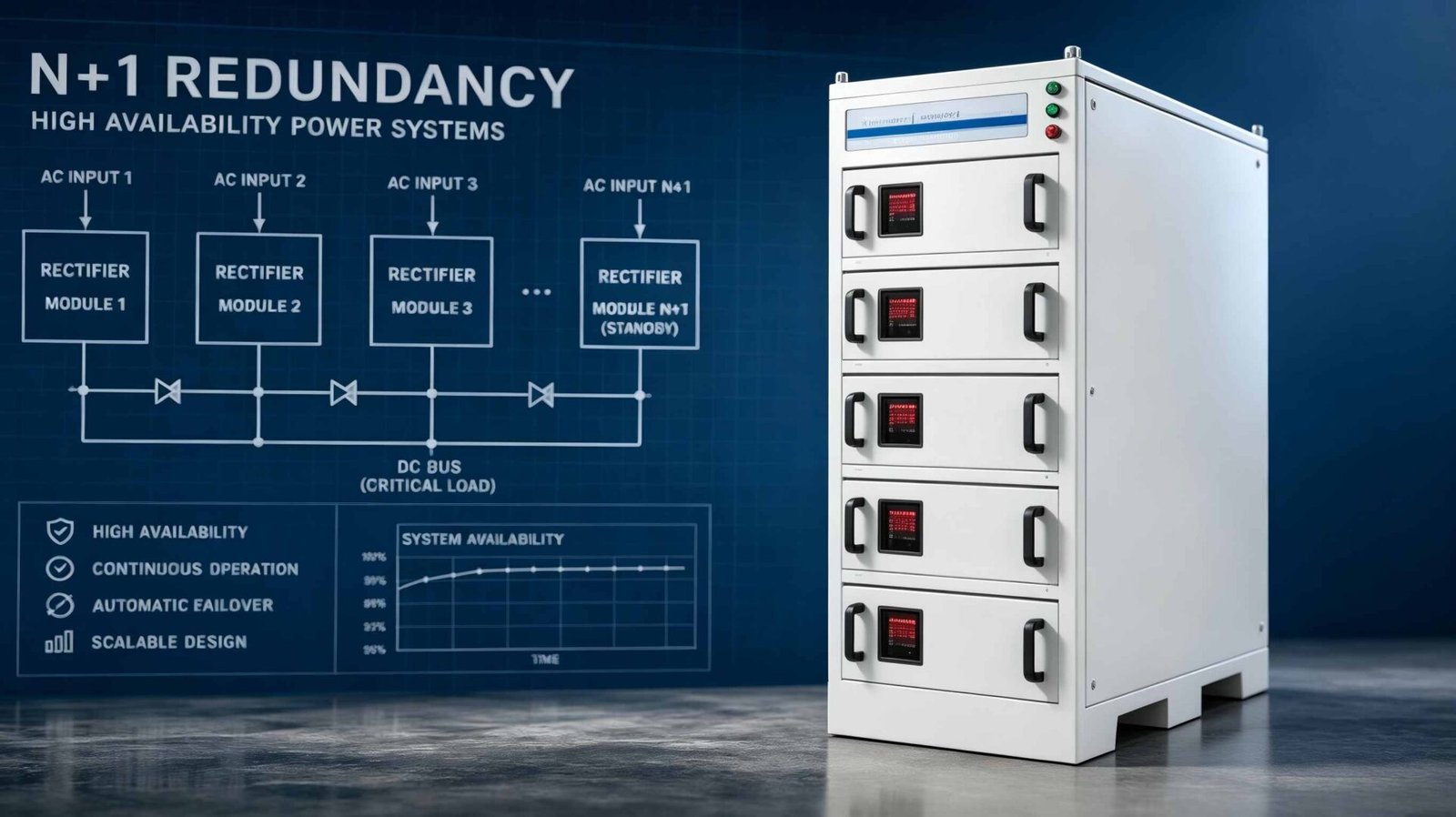
Parallel rectifier operation with N+1 reduncancy is a power system design strategy that connects multiple rectifier modules to share load current equally, ensuring continuous operation when one module fails, achieving 99.97%+ system availability for mission-critical electroplating and anodizing applications. According to EN 62477-1:2022 (Power electronics converter systems – Safety requirements), parallel operation must maintain current sharing imbalance below 5% and provide redundant capacity equal to the largest single module. A parallel rectifier system is a multi-module DC power architecture that distributes total current demand across N identical modules (N+1 configuration provides one spare module), achieving fault tolerance, scalable capacity expansion, and reduced single-point-of-failure risk in high-current applications (5,000A-200,000A).
Why Parallel Operation Is Essential for High-Current DC Power Systems (>5,000A)
Single-module rectifiers above 5,000A face significant engineering challenges: larger transformer cores, higher short-circuit forces, more complex cooling systems, and single-point failure risk. A single 10,000A/12V rectifier (120kW) represents a single point of failure—if it fails, the entire production line stops, costing $3,000-$12,000 per hour in downtime for typical electroplating facilities.
Parallel operation advantages:
- Scalability: Add modules incrementally (e.g., 2,000A modules × 5 = 10,000A system) vs. custom large-frame design
- Redundancy: N+1 configuration allows continued operation at reduced capacity if one module fails
- Maintenance: Individual modules can be serviced without shutting down the entire system
- Logistics: Smaller modules are easier to transport, install, and replace (fit through standard doorways)
- Cost: Modular systems have 15-25% lower total cost of ownership over 10 years vs. single large rectifier
| System Type | Current Range | Reliability (Annual Downtime) | Redundancy Option | Typical Cost (USD) |
|---|---|---|---|---|
| Single Rectifier | 50-5,000A | 4-8 hours (99.91-99.96%) | None (SPOF) | $8,000-$45,000 |
| Parallel (N) | 5,000-50,000A | 2-4 hours (99.95-99.98%) | Limited (manual bypass) | $45,000-$350,000 |
| Parallel (N+1) | 5,000-100,000A | 0.5-2 hours (99.98-99.995%) | Yes (auto switch) | $55,000-$420,000 |
| Parallel (N+2) | 10,000-200,000A | <0.5 hours (99.995%+) | Yes (dual redundancy) | $120,000-$800,000 |
Current Sharing Control: The #1 Challenge in Parallel Rectifier Systems
When N modules operate in parallel, they must share the total load current equally (within 5% deviation per EN 62477-1). Unequal current sharing causes:
– Overload tripping: One module carries >110% while others carry <80%
– Thermal imbalance: Overloaded module runs 15-25°C hotter, reducing IGBT lifetime by 40-60%
– Nuisance derating: System capacity drops by 20-40% due to one module’s temperature alarm
Three Current Sharing Methods Compared
| Method | Accuracy | Response Time | Complexity | Best For |
|---|---|---|---|---|
| Droop Control (Voltage Droop) | ±8-12% | 10-50ms | Low (built-in) | Small systems (<10 modules) |
| Active Current Sharing (Analog Bus) | ±3-5% | 1-5ms | Medium (wiring) | Medium systems (5-20 modules) |
| Digital Master-Slave (CAN/RS485) | ±1-3% | 0.5-2ms | High (communication) | Large systems (20+ modules) |
QEEHUA’s digital master-slave control (CAN bus communication between modules) achieves ±1.5% current sharing accuracy across 1-50 parallel modules. Each module measures its own output current via precision Hall-effect sensors (0.5% accuracy) and adjusts its voltage setpoint to match the master module’s current setpoint. The system automatically reconfigures if the master module fails—any slave can become the new master within 50ms.
N+1 Redundancy Design: How Many Spare Modules Do You Need?
The “N+1” in N+1 reduncancy means: N modules carry the normal load, and 1 additional module provides redundancy. If any single module fails, the remaining N modules can still carry the full load (with possible reduced margin).
N+1 Redundancy Calculator
Formula: System Capacity = (N + 1) × Module Rating
Normal Load: N × Module Rating = 80-90% of System Capacity (20-10% margin)
After Failure: N × Module Rating = 100% of required load (0% margin, full capacity maintained)
Example: 10,000A required load
– Option A: 5 × 2,500A modules (N=4, +1 spare) = 12,500A system, 10,000A normal (80% load)
– Option B: 6 × 2,000A modules (N=5, +1 spare) = 12,000A system, 10,000A normal (83% load)
– After 1 module fails: Option A has 4 × 2,500A = 10,000A (100%); Option B has 5 × 2,000A = 10,000A (100%)
| Required Load (A) | Module Size (A) | N+1 Configuration | System Capacity (A) | Normal Load % | Post-Failure Capacity |
|---|---|---|---|---|---|
| 5,000 | 1,250 | 4+1 | 6,250 | 80% | 5,000A (100%) |
| 10,000 | 2,000 | 5+1 | 12,000 | 83% | 10,000A (100%) |
| 20,000 | 2,500 | 8+1 | 22,500 | 89% | 20,000A (100%) |
| 50,000 | 5,000 | 10+1 | 55,000 | 91% | 50,000A (100%) |
| 100,000 | 10,000 | 10+1 | 110,000 | 91% | 100,000A (100%) |
Real-World Solution: Turkish Anodizing Facility Achieves 99.98% Uptime with N+2 Redundancy
The Challenge: A Istanbul-based aluminum anodizing facility (Type III hard anodizing, 15,000A × 24V) was experiencing 12-18 hours of unplanned downtime per year with their single 18,000A rectifier. Each downtime incident cost ₺48,000 ($1,600) per hour in lost production and rushed rework. Their customer contracts included 99.9% on-time delivery penalties of €12,000 per incident.
The Solution: QEEHUA designed an N+2 redundant parallel system: 10 × 1,800A IGBT rectifier modules (9 active + 1 hot standby, expandable to N+2 by activating standby). System capacity: 18,000A (9 modules) with 2-module redundancy.
- Uptime improved from 99.79% (17.4 hours downtime/year) to 99.98% (0.96 hours/year)
- Downtime cost saved: (17.4 – 0.96) × $1,600 = $26,304/year
- Contract penalty avoided: 0 penalty incidents vs. 3-5/year previously = $36,000-$60,000 saved/year
- ROI period: 22 months (equipment cost $95,000 ÷ $62,304/year savings)
- Current sharing accuracy: ±1.8% across all 10 modules (digital master-slave control)
QEEHUA Rectifier — Your Trusted Industrial Power Supply Partner
✓ ISO 9001:2015 Certified Manufacturing
✓ CE & RoHS Compliant Products
✓ 2,000+ Industrial Installations Worldwide
✓ Serving Clients in 80+ Countries Across 6 Continents
✓ 18-Month Standard Warranty with Lifetime Technical Support
✓ Remote Diagnostics & On-Site Service Available
Designing a Parallel Rectifier System with N+1 Redundancy?
Our technical team provides free parallel system design, redundancy analysis, and current-sharing simulations. Get your custom configuration within 24 hours.
Frequently Asked Questions About Parallel Rectifier Operation
What is the maximum number of rectifier modules that can operate in parallel?
Theoretically, there is no upper limit to the number of parallel modules, but practical constraints limit most industrial systems to 20-50 modules. Key limiting factors include: control system communication bandwidth (CAN bus has node limits), current sharing bus impedance (voltage drop affects accuracy beyond 30-40 modules), physical busbar design (proximity requirements for equal cable lengths), and protection coordination (selective tripping becomes complex). QEEHUA’s digital control system supports up to 50 modules in parallel with ±2% current sharing accuracy. For systems requiring >50 modules (100,000A+ applications), we recommend multiple independent DC buses with load sharing contactors.
How does N+1 redundancy compare to N+2 for critical applications?
N+1 redundancy provides one spare module—if one module fails, the system continues at full capacity but with no remaining redundancy (if a second module fails before repair, the system derates). N+2 redundancy provides two spare modules—even after one failure, the system retains one spare. For mission-critical applications (continuous process, high downtime cost >$5,000/hour), N+2 is recommended. For standard applications, N+1 provides sufficient protection at 15-20% lower cost. Semiconductor manufacturing and continuous chemical processing typically specify N+2, while general electroplating and anodizing use N+1.
What happens when a parallel module fails? Does the system shut down?
No—with N+1 or N+2 redundancy, the system continues operating. When a module failure is detected (overcurrent, overtemperature, or communication loss), the control system: (1) Isolates the failed module via DC contactor (50-100ms), (2) Redistributes the failed module’s current to remaining modules (200-500ms), (3) Activates alarm notification to operators, (4) Continues operation with reduced redundancy. The system does NOT shut down. Operators have 24-48 hours to replace the failed module before the next failure would cause derating. According to IEC 62477-1 safety standards, redundant systems must maintain safe operation during single-point failures.
Can I mix different rectifier models or power ratings in a parallel system?
No—mixing different models, power ratings, or manufacturers in a parallel system is strongly discouraged and often impossible with active current sharing. Modules must be identical in: (1) Rated output voltage (±0.5% tolerance), (2) Rated output current, (3) Control topology (droop characteristics must match), (4) Communication protocol (for digital current sharing). Mixing creates unequal current sharing (>15% deviation), thermal imbalance, and protection coordination problems. If you must expand an existing system with different modules, use a separate DC bus with OR-ing diodes or a static transfer switch—do NOT parallel them directly. QEEHUA provides legacy module compatibility checks for system expansions.
How much does an N+1 parallel rectifier system cost vs. a single large rectifier?
An N+1 parallel system typically costs 10-25% more than a single large rectifier of equivalent capacity, but offers 30-50% lower lifecycle cost due to redundancy and maintainability. Example: 10,000A/12V system. Single rectifier: $65,000 (no redundancy). N+1 parallel (5×2,500A): $78,000 (20% premium). However, the parallel system’s N+1 redundancy prevents $36,000-$72,000/year in downtime costs, paying back the 20% premium in 2-4 months. Additionally, modular systems have 40-60% lower repair costs (replace one module vs. entire unit) and 15-30% lower shipping/installation costs.
What are the protection challenges in parallel rectifier systems?
Parallel systems have complex protection coordination requirements: (1) Module-level protection (each module needs individual overcurrent, overtemperature, and short-circuit protection), (2) System-level protection (total system overcurrent and DC bus fault protection), (3) Selectivity (only the faulted module should trip, not the entire system). Common approaches: (a) Electronic circuit breakers with communication-based selectivity, (b) Fast-acting fuses (semiconductor-rated, <10ms clearing time), (c) Fault current limiting reactors. QEEHUA systems use IEC 60269-4 compliant semiconductor fuses (aR type) with 10-20kA interrupting capacity and selective coordination across all modules.
Which communication protocol is best for parallel rectifier control systems?
CAN bus (Controller Area Network, IS0 11898) is the industry-standard protocol for parallel rectifier control due to its deterministic communication (≤1ms latency), noise immunity (differential signaling), and multi-master capability. RS-485 (Modbus RTU) is an alternative but has longer latency (5-20ms) and single-master limitation. EtherCAT or EtherNet/IP are used in high-end systems requiring integration with plant automation (PLC/SCADA) but add 20-40% cost. QEEHUA uses CAN bus for intra-module communication and RS-485/Modbus TCP for external SCADA interface. This hybrid approach provides fast parallel control with flexible plant integration.
Conclusion: Five Design Principles for Reliable Parallel Rectifier Systems
- Principle 1: Size for N+1 minimum — Always include at least one redundant module. For critical applications, N+2 provides better protection.
- Principle 2: Use digital current sharing — Droop control is insufficient for >5 modules. Invest in CAN/RS485 active sharing (±2-3% accuracy).
- Principle 3: Match module characteristics — All parallel modules must be identical model, same firmware version, same cable lengths.
- Principle 4: Plan maintenance access — Design physical layout for easy module removal/replacement without system shutdown.
- Principle 5: Integrate with SCADA — Monitor individual module currents, temperatures, and alarm status via Modbus/OPC for proactive maintenance.
QEEHUA’s parallel rectifier systems (1,000A-200,000A total capacity) feature digital master-slave control, N+1/N+2 redundancy options, and full IEC 62477-1 / IEC 61000-6-2 compliance. Our technical team provides complete system design, including current sharing analysis, redundancy configuration, and protection coordination study.
Ready to Design Your Parallel Rectifier System?
Download our free Parallel System Design Guide and N+1 Calculator. QEEHUA technical team responds within 24 hours with custom configuration.