Electroplating rectifiers are the core power supply units for surface treatment processes such as PCB manufacturing, electroplating processing, and anodic oxidation. In precision processes like copper foil plating, gold plating, and silver plating, the performance of the rectifier directly determines the coating quality and production efficiency. This article focuses on copper foil plating—a critical application scenario—and details the key points of equipment selection and configuration.
1. Overview of Copper Foil Electroplating
What is Copper Foil Electroplating?
Copper foil electroplating is the process of depositing a copper layer onto a substrate surface using electrochemical methods in PCB (Printed Circuit Board) manufacturing. Based on application, it is categorized into:
- Electrolytic Copper Foil: Used in Copper Clad Laminate (CCL) manufacturing.
- Pattern Plating: Increasing the thickness of the copper layer on circuits after etching.
Key Process Parameters for Copper Foil Plating
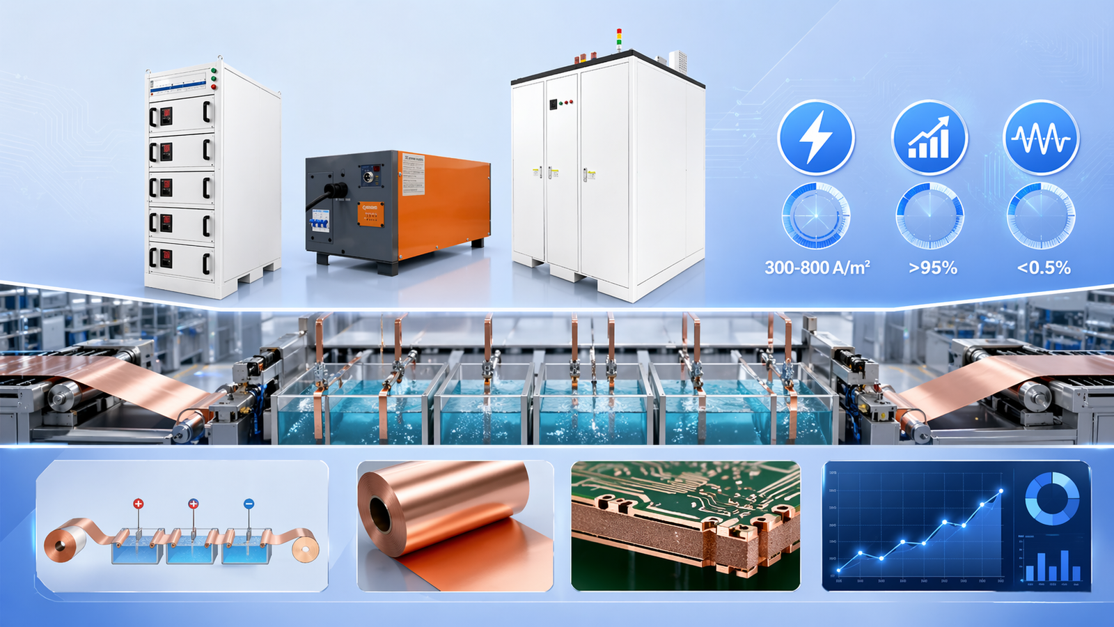
| Parameter | Typical Range | Impact |
|---|---|---|
| Current Density | 300 – 800 A/m² | Determines plating speed and coating quality |
| Additive Concentration | Per Formulation | Affects grain crystallization and brightness |
| Temperature | 20 – 30℃ | Affects current efficiency and crystallization |
| Sulfuric Acid Conc. | 50 – 150 g/L | Affects conductivity and throwing power |
2. Current Density: The Core Control Parameter
Why is Current Density Critical?
Current density (A/m²) refers to the current intensity per unit area. It directly impacts:
- Deposition Speed: Higher density results in faster plating.
- Grain Structure: Excessive density leads to roughness; insufficient density may cause burning.
- Throwing Power: Low density areas may suffer from poor coverage.
Current Density and Process Matching Table
| Copper Foil Type | Current Density (A/m²) | Rectifier Specification Suggestion |
|---|---|---|
| Standard Electrolytic | 300 – 500 | 500-800 A/m² × Area |
| High Ductility | 200 – 400 | Focus on low-density uniformity |
| Ultra-thin (<9μm) | 150 – 300 | Requires high-precision constant current control |
| Aerospace Grade | 400 – 600 | High quality and high stability |
Practical Calculation Example
Scenario: A PCB plant needs to plate 0.5oz copper (thickness approx. 18μm) on a substrate.
Given:
- Substrate Area: 1m² (10,000 cm²)
- Target Thickness: 18μm (0.0018 cm)
- Plating Time: 30 minutes (0.5h)
- Copper Density: 8.96 g/cm³
- Copper Electrochemical Equivalent: 1.186 g/A·h
Calculation:
- Mass of copper: 10,000cm² × 0.0018cm × 8.96g/cm³ = 161.28g
- Required charge: 161.28g ÷ 1.186g/A·h = 135.98 A·h
- Required current: 135.98 A·h ÷ 0.5h = 272A
- Current Density: 272A / 1m² = 272 A/m² (or 2.72 A/dm²)
3. Core Performance Indicators of Rectifiers
Efficiency > 95%
QEEHUA rectifiers utilize advanced SCR control technology, with full-load efficiency stable at 95-97%. For a line producing 5 million m²/year, every 1% increase in efficiency can save approximately 250,000 RMB in annual electricity costs.
Ripple Coefficient < 0.5%
Low ripple is essential for high-quality copper surfaces. For decorative gold plating, requirements are often <0.5%, while connector plating and wafer plating require <0.3% and <0.1% respectively.
4. Configuration Schemes
Scheme 1: Standalone Configuration
Best for standard PCB production lines with fixed tank positions.
Tank Size: 1500×800×1200mm
Plating Area: Approx. 12m²
Suggested Current: 12m² × 500 A/m² = 6000A
Recommended Rectifier: QEEHUA SCR-6000A/24V
Scheme 2: Parallel Redundant Configuration
Best for large-format copper foil or wide plating lines. Offers backup capability; production doesn’t stop if one unit fails.
5. Troubleshooting and Selection Risks
⚠️ Risk 1: Ignoring Actual Operating Range – Some low-cost units only reach rated current at maximum voltage. Ensure the equipment can output full current at low voltages.
⚠️ Risk 2: Power Factor and Harmonics – Low power factor leads to grid penalties. Choose equipment with Power Factor > 0.92 and Harmonic THD < 15%.
⚠️ Risk 3: Protection Levels – Plating workshops are humid and corrosive. Select rectifiers with IP54 rating or higher with anti-corrosion coatings.
6. QEEHUA Rectifier Product Line
| Series | Voltage | Current | Efficiency | Ripple | Application |
|---|---|---|---|---|---|
| SCR Electrolytic | 0-45V | 0-500KA | >95% | <0.5% | Copper Foil, Electrolysis |
| HF Switching | 0-24V | 0-80KA | >96% | <3% | Precision Plating |
| Modular | 0-12V | 0-20KA | >95% | <1% | Multi-variety Production |
As a manufacturer with 15 years of experience, QEEHUA provides customized solutions for clients in over 40 countries. Contact us for a free selection plan for your process.