
Synchronous Rectifier Applications
Discover how QEEHUA's advanced electroplating rectifiers and chemical fluid transfer solutions revolutionize PCB manufacturing, surface treatment, electroplating processes, and semiconductor production with unparalleled precision and efficiency.
Printed Circuit Boards
High-precision PCB manufacturing solutions
Surface Treatment Industry
Advanced coating and finishing processes
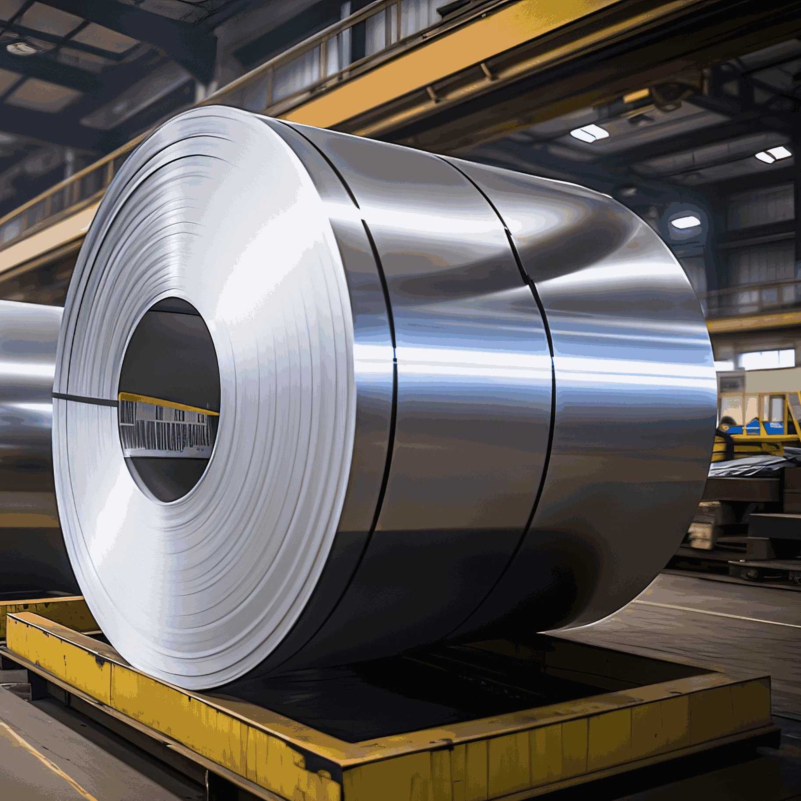
Electrolytic Copper Foil
Ultra-thin precision foil production
Hydrogen Production by
Electrolysis systems for clean energy

Petroleum Refining
Industrial refinery applications

Environmentally Friendly Water
Sustainable water treatment solutions

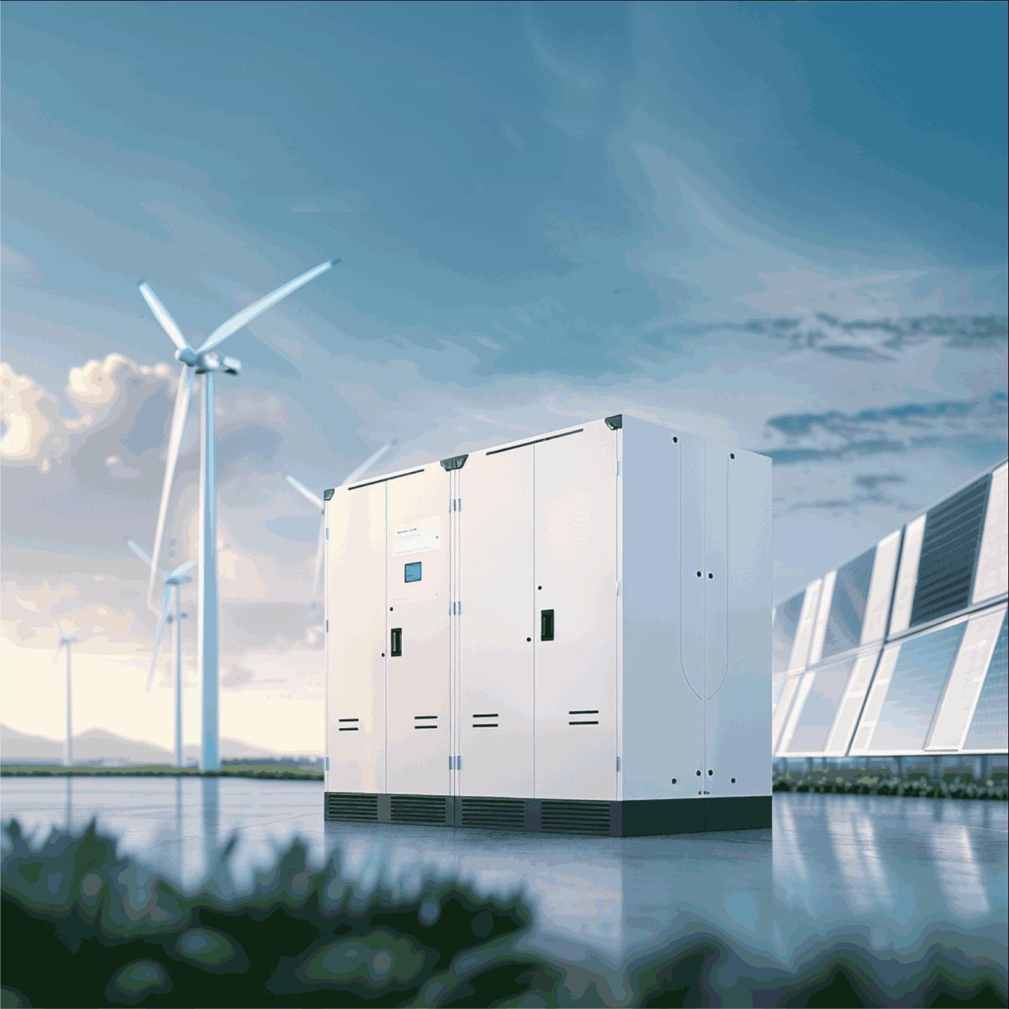
Photovoltaic Industry
Solar panel manufacturing solutions

Rare Earth Smelting
Specialized metal processing systems
Synchronous Rectifier in Lithium Copper Foil Production
Critical applications in ultra-thin copper foil manufacturing for lithium battery electrodes, achieving 6-12μm thickness precision through advanced electrolytic processes.
Production Process Overview
Electrolytic Deposition
Copper ions reduced at cathode in sulfuric acid electrolyte, forming ultra-thin foil layers
Thickness Control
Precise current density regulation ensures 6-12μm uniform thickness across the entire foil
Parameter Optimization
Continuous monitoring and adjustment of electrolytic parameters for optimal production
Technical Advantages
High Efficiency
• Reduced energy consumption
• Lower heat generation
• Extended equipment lifespan
Precision Control
• Fast response speed
• Long-term stability
• Uniform foil thickness
Process Adaptability
• Multi-channel output
• Intelligent control
• Automated management
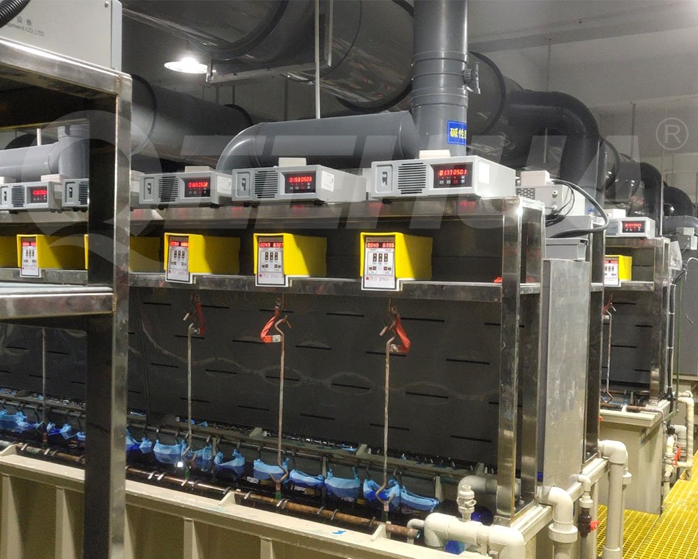
Electrolytic Copper Foil Production
Surface Treatment Process
Roughening Treatment
Enhanced surface texture for improved battery performance and adhesion properties
Anti-oxidation Coating
Protective layer application to prevent oxidation during storage and handling
Quality Testing
Electrochemical processing for comprehensive quality control and validation
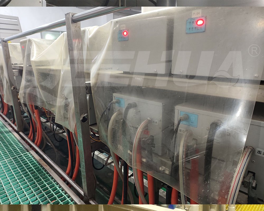
Water-Cooled Synchronous Rectifier in PCB Electroplating
Advanced water-cooled systems delivering superior thermal management and precision control for copper and tin electroplating in printed circuit board manufacturing.
PCB Electroplating Process Flow
Copper Electroplating Process
Chemical Copper Plating
Forms thin conductive layer (0.2-0.5μm) as foundation for electroplating
Electrolytic Copper Plating
Thickens conductive layer to 25-40μm with 1-3 A/dm² current density
Copper Plating Parameters
Tin Electroplating Process
Pre-plating Protection
Applies protective tin layer before hot air leveling process
Surface Treatment
Provides anti-oxidation properties and enhanced solderability
Tin Plating Parameters
Water-Cooled System Advantages
Synchronous Rectification Technology
Water Cooling System Design
Cooling Circuit Configuration
Primary Circuit
Deionized water circulation for direct component cooling
Secondary Circuit
Cooling tower or chiller unit for heat rejection
Flow Control
Ensures uniform cooling distribution
Temperature Monitoring
Prevents condensation and overheating
Heat Sink Design
Material Selection
Aluminum alloy or copper for optimal thermal conductivity
Fin Structure
Optimized heat dissipation surface area
Flow Channel Design
Minimized pressure loss for efficient cooling
Insulation Treatment
Electrical safety assurance
Electroplating Power Supply in Photovoltaic Applications
Specialized power solutions for solar cell manufacturing, featuring multi-layer Ni/Cu/Ag electroplating processes with pulse and high-frequency switching technologies.
Silicon Wafer Electroplating Process
Multi-Layer Plating Structure
• Copper Plating: Conductivity enhancement and resistance reduction
• Silver Plating: Final current collection electrode formation
• Tin Plating: Protection and soldering layer
Process Flow
1. Silicon Wafer Cleaning
2. Seed Layer Deposition
3. Photoresist Coating
4. Exposure & Development
5. Electroplating Process
6. Photoresist Stripping
7. Cleaning & Drying
8. Quality Inspection
Copper Plating (Cu)
Process Parameters
Application Benefits
• Improved fill factor
• Enhanced current carrying capacity
Nickel Plating (Ni)
Process Parameters
Application Benefits
• Improves contact stability
• Enhanced adhesion properties
Silver Plating (Ag)
Process Parameters
Application Benefits
• Reduces contact resistance
• Improves light reflectance
Advanced Power Supply Technologies
Pulse Power Supply Characteristics
Pulse Parameters
Technical Advantages
• Reduced stress concentration
• Enhanced coating uniformity
• Lower surface roughness
High-Frequency Switching Power Supply
Technical Specifications
PERC Solar Cells
• Cost Reduction: 15-20% manufacturing cost savings
• Efficiency Gain: 0.2-0.3% performance improvement
• Fine Line Technology: Grid line width <30μm
TOPCon Solar Cells
• Low Temperature Process: <60°C processing temperature
• Passivation Protection: Avoids passivation layer damage
• High Aspect Ratio: Deep plating capability
HJT Solar Cells
• Flexible Plating: Adapts to thin wafer processes
• Transparent Conductive Layer: Maintains optical properties
• Low Damage Process: Protects amorphous silicon layers
Application Case Studies
Discover how QEEHUA's synchronous rectifier technology delivers exceptional results in real production environments worldwide.
High Efficiency Achievement
Energy-saving effect and conversion efficiency test
Challenge
Measure the rectifier's terminal output voltage and current (currently directly referencing the system's displayed current), as well as the three-phase input active power. The efficiency calculation formula is (actual output voltage * actual output current) / input active power (external connection terminals and electrolytic cell losses are not included to ensure the objectivity of the data), (currently, the current efficiency is calculated by recording instantaneous current voltage and instantaneous input power)
Test Data and Efficiency Results
Performance comparison between QEEHUA power supplies and original equipment:
| Equipment Type | Input Power (kW) | Output Voltage (V) | Output Current (A) | Output Power (kW) | Efficiency |
|---|---|---|---|---|---|
| QEEHUA Air-Cooled Synchronous | 5.8 | 11.7 | 481 | 5.63 | 97% |
| QEEHUA Air-Cooled Synchronous | 4.48 | 11.7 | 361 | 4.22 | 94.2% |
| Original 1st Slot High-Frequency Switch | 5.76 | 11.9 | 389 | 4.63 | 80.3% |
| Original 17th Slot Air-Cooled Switch | 3.57 | 13.0 | 211 | 2.74 | 76.8% |
Average Power Comparison Test
Superior Product Quality
Comparison of coating improvement effects
Challenge
Within the same time frame, using the same plating material, workpiece, and rectifier in constant current mode, controlling the same current and voltage, compare the film thickness difference, uniformity, plating speed, and other product values of the two rectifiers
Performance Comparison Test Results
Comparative analysis of coating quality between traditional high-frequency rectifiers and QEEHUA electroplating rectifiers:
| Test Parameters | Traditional High-Frequency | QEEHUA Rectifier |
|---|---|---|
| ZnNi Layer Thickness |
Avg: 7.960μm
Min: 7.03μm | Max: 9.88μm
|
Avg: 9.602μm
Min: 8.64μm | Max: 10.2μm
|
| Zn Layer Ratio |
Avg: 83.96%
Min: 83.1% | Max: 84.6%
|
Avg: 84.12%
Min: 83.8% | Max: 84.4%
|
| Ni Layer Thickness |
Avg: 16.04μm
Min: 15.4μm | Max: 16.9μm
|
Avg: 15.88μm
Min: 15.6μm | Max: 16.2μm
|
QEEHUA vs Traditional High-Frequency Coating Performance
Integrated Power Supply Solutions
Complete electroplating power solutions tailored for each application, featuring our advanced synchronous rectifier technology with intelligent control and monitoring capabilities.
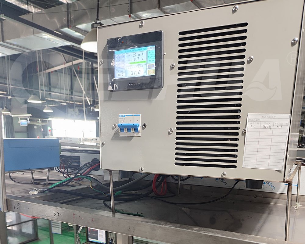
QE-SYHM-W
Stable water-cooled rectifier engineered for long-term, heavy-duty plating lines.
QE-SYHS-A
Air-Cooled Synchronous Rectifier for Stable, Energy-Efficient Electroplating
QE-SYHS-W
Stable High-Current Output & Efficient Cooling for Industrial Electroplating
QE-SYHM-A
Flexible, Scalable & Easy-Maintenance DC Power Supply Air-Cooled Modular Rectifier for Electroplating
QE-SYHD-W
Dual Water-Cooled Synchronous Rectifier for PCB & Electroplating
QE-SCHS-A
Achieve More Uniform PCB Plating with Low-Ripple High-Frequency Rectifier
System Configuration Options
Large-Scale Production Line
Ideal Applications
Automotive production lines, large PCB facilities, continuous lithium copper foil manufacturing
Pilot & R&D Line Configuration
Ideal Applications
Research facilities, pilot production, process development, small-scale specialized plating
Experience QEEHUA's Advanced Technology
Join industry leaders worldwide who trust QEEHUA's synchronous rectifier technology for superior efficiency, precision, and reliability in their electroplating operations.