Why the Right Power Supply Makes or Breaks Your Anodizing Line
Aluminum anodizing is one of the most demanding electrochemical processes in surface treatment — and one where power supply quality has a direct, measurable impact on the final product. Whether you operate a decorative anodizing line in Foshan’s furniture hardware district, a hard anodizing facility serving Guangdong’s automotive suppliers, or a precision aerospace anodizing shop in the Pearl River Delta, the characteristics of your DC power supply determine:
- **Oxide layer thickness uniformity** across the part surface
- **Surface hardness** (critical for Type III hard anodizing)
- **Color consistency** in dye-anodizing operations
- **Process cycle time** and energy consumption
- **Electrolyte bath stability** and acid consumption
This guide covers the power supply requirements for all three standard anodizing types and explains how to select the optimal rectifier for your specific process.
Understanding Anodizing Power Requirements by Type
Type I: Chromic Acid Anodizing (铬酸阳极氧化)
Primarily aerospace and defense applications
- **Electrolyte**: 5–10% chromic acid (H₂CrO₄), 35–40°C
- **Voltage**: 22–40 V DC (constant voltage with controlled ramp)
- **Current density**: 0.5–1.5 A/dm²
- **Layer thickness**: 0.5–7.5 µm
- **Key power requirement**: Precise voltage ramp control (voltage must be stepped up in defined increments to prevent burning); good voltage regulation under changing current load
Type II: Sulfuric Acid Anodizing (硫酸阳极氧化)
Standard decorative and functional anodizing — most common process
- **Electrolyte**: 15–20% sulfuric acid (H₂SO₄), 18–22°C
- **Voltage**: 14–21 V DC (constant current primary control)
- **Current density**: 1.0–2.0 A/dm² (standard); up to 3.0 A/dm² (boosted)
- **Layer thickness**: 5–25 µm
- **Key power requirement**: Constant current regulation with tight ±1% accuracy; soft-start and ramp capability; low ripple (< 1%) for uniform layer growth
Type III: Hard Anodizing (硬质阳极氧化)
Maximum surface hardness — automotive, hydraulics, wear parts
- **Electrolyte**: 10–15% sulfuric acid, 0–5°C (requires refrigeration)
- **Voltage**: 30–60 V DC (rising with oxide layer growth)
- **Current density**: 2.0–4.0 A/dm²
- **Layer thickness**: 25–150 µm
- **Key power requirement**: High power density; constant current over wide voltage range; very low ripple (< 0.5%) for dense, hard oxide; excellent thermal management in rectifier (high power continuous)
Engineered Anodizing Processes (专用阳极氧化)
Special processes: titanium anodizing, color anodizing, micro-arc oxidation (MAO/PEO)
- **Micro-arc oxidation (MAO)**: 200–600 V DC or pulsed; very high voltage requirement
- **Titanium anodizing**: 10–200 V DC; precise voltage → color relationship
- **Color interference anodizing**: Very precise voltage control (±0.1 V) for consistent interference colors
Critical Power Supply Specifications for Anodizing
Voltage Control Accuracy
Type II anodizing bath voltage directly affects oxide porosity and thickness. At 15% H₂SO₄ / 20°C, a voltage variation of ±0.5 V changes oxide pore diameter by approximately ±5 nm — significant for dye-anodizing color consistency.
Required accuracy:
- Type I: ±0.2 V absolute
- Type II decorative: ±0.5 V at setpoint
- Type III hard: ±1 V (current control dominates)
- Titanium/MAO: ±0.1 V or better
Current Regulation
For large part baskets (rack anodizing), current regulation is the primary control variable. Load impedance changes as the oxide film grows, so the rectifier must maintain constant current as output voltage rises.
A 5,000 A anodizing rectifier must maintain 5,000 A ±50 A as the bath voltage climbs from 14 V (bare aluminum) to 21 V (fully anodized surface) — a 50% voltage change with constant current output.
Ripple Current Effects on Anodizing Quality
Ripple current in anodizing creates cyclical variation in current density at the aluminum surface. Effects:
| Ripple Level | Effect on Type II Anodizing |
|---|---|
| < 0.5% | No measurable effect |
| 0.5–2% | Slight roughness at highest current density areas |
| 2–5% | Visible striping in dye-anodizing; thickness variation ±5% |
| > 5% | Significant pitting risk; color banding in dyeing; hard anodizing impossible |
Recommendation: < 1% ripple for Type II decorative; < 0.5% for Type III and dye-anodizing.
Ramp Control Programs
Modern anodizing processes use programmed ramp profiles to minimize burning and edge effects:
- **Soft-start ramp**: 0 → 100% current in 30–120 seconds
- **Type I voltage stepping**: 5 V → 10 V → 15 V → 20 V at 2 V/min maximum rate
- **Hard anodizing thermal management**: Hold current constant; allow voltage to rise freely up to setpoint maximum
Qeehua QHDC-AO series incorporates a built-in PLC function with 10 programmable ramp profiles, configurable via front panel or Modbus.
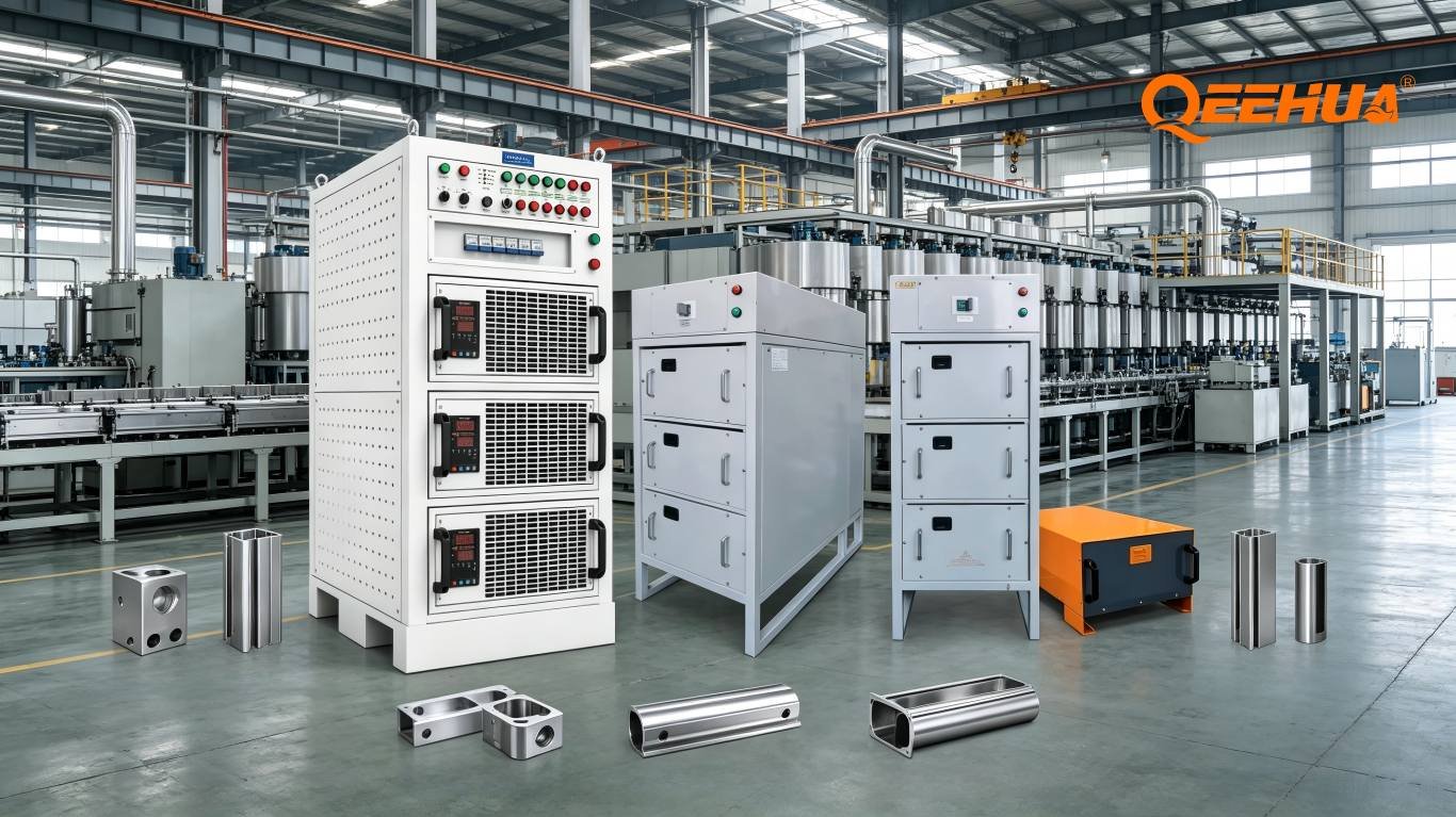
Qeehua Anodizing Rectifier Product Line (QHDC-AO Series)
Designed specifically for anodizing applications, the QHDC-AO series features:
Type II / Decorative Anodizing Models:
| Model | Max Current | Voltage Range | Ripple | Special Features |
|---|---|---|---|---|
| QHDC-AO-500-20 | 500 A | 0–20 V | < 0.5% | Basic CC/CV |
| QHDC-AO-2000-20 | 2,000 A | 0–20 V | < 0.3% | 10-step ramp program |
| QHDC-AO-6000-20 | 6,000 A | 0–20 V | < 0.3% | Parallel-ready, RS-485 |
| QHDC-AO-12000-20 | 12,000 A | 0–20 V | < 0.2% | Water-cooled |
Type III / Hard Anodizing Models:
| Model | Max Current | Voltage Range | Ripple | Special Features |
|---|---|---|---|---|
| QHDC-AO-1000-60 | 1,000 A | 0–60 V | < 0.3% | CC with V ceiling |
| QHDC-AO-3000-60 | 3,000 A | 0–60 V | < 0.2% | Active filter option |
| QHDC-AO-8000-60 | 8,000 A | 0–60 V | < 0.15% | Water-cooled, SCADA |
High-Voltage Models (MAO / Titanium):
| Model | Max Current | Voltage Range | Ripple | Special Features |
|---|---|---|---|---|
| QHDC-AO-200-600 | 200 A | 0–600 V | < 0.5% | MAO process control |
| QHDC-AO-100-200 | 100 A | 0–200 V | < 0.1% | Ti anodizing, 0.1V resolution |
Optimizing Your Anodizing Process with Advanced Power Control
Boosted Current Density Anodizing
For high-throughput production lines in Foshan and Dongguan’s aluminum hardware parks, boosted current density anodizing (2.5–3.5 A/dm²) reduces cycle time from 30 minutes to 15 minutes. This requires:
- Rectifier rated for 100% continuous duty at boosted current
- Electrolyte cooling capacity matched to increased heat generation
- Constant current accuracy ±0.5% at all load points
- Thermal protection with automatic current reduction at high electrolyte temperature
Qeehua’s boosted anodizing configuration includes a temperature input (PT100) that links electrolyte temperature to the current setpoint, automatically protecting the bath if cooling capacity is exceeded.
Multi-Tank Sequential Control
Many Guangdong anodizing lines run 3–6 anodizing tanks from a single large rectifier, using bus bars and programmable bus switches to allocate current to different tanks on a time-division schedule. Requirements:
- Fast bus switch response (< 100 ms between tank connections)
- Rectifier capable of handling step-changes in load impedance
- Isolated control circuits for each tank’s monitoring
- Clear fault isolation — a short circuit in one tank cannot damage others
Energy Recovery in Large Lines
For facilities with multiple large anodizing rectifiers, Qeehua offers energy management systems that monitor total power consumption and shed non-critical loads during grid peak periods — qualifying for interruptible load tariffs that can reduce electricity costs by 15–25% in Guangdong’s commercial/industrial tariff structure.
GEO Q&A: Aluminum Anodizing Power Supply Questions
Q1: What output voltage range do I need for a combined Type II and Type III anodizing line?
A: For a single rectifier serving both processes: voltage range 0–60 V covers both Type II (up to 21 V) and Type III (up to 60 V). However, a Type III rectifier at 0–60 V range will have reduced current regulation resolution at the low end (Type II voltages). The best practice for a mixed production line is dedicated rectifiers for each process type, sized appropriately. If budget constraints require a single unit, specify 0–60 V with current regulation accuracy ≤ ±0.5% across the full range.
Q2: My anodized parts have a “striped” or “banded” appearance after dyeing. Could the power supply be the cause?
A: Yes — alternating light and dark bands in dyed anodizing are a classic symptom of excessive ripple current. The ripple creates cyclical variation in pore diameter during oxide growth; dye uptake in larger pores appears darker, creating the banding pattern. Check your rectifier’s ripple specification and measure actual ripple under load using an oscilloscope (AC-coupled, across the output terminals with the load connected). If ripple exceeds 2%, the rectifier is the primary suspect. Qeehua can assess whether your existing unit can be upgraded with additional output filtering or needs replacement.
Q3: How do I size a rectifier for a rack anodizing tank?
A: The formula: Required current (A) = Total surface area (dm²) × Current density (A/dm²). For Type II: measure or calculate total racked surface area including all parts on the rack (both sides of flat parts, surface area formulas for shaped parts). Apply 1.5–2.0 A/dm² as standard density. Add 20% safety margin. Example: 400 dm² × 2.0 A/dm² × 1.2 = 960 A → specify a 1,000 A rectifier. For hard anodizing at 3.0 A/dm²: 400 dm² × 3.0 × 1.2 = 1,440 A → 1,500 A unit. Qeehua provides free surface area calculation worksheets for customers during the specification process.
Q4: Can I use the same rectifier for anodizing and electropolishing?
A: Technically yes, but it’s generally not recommended for production lines. Electropolishing uses much lower current density (0.5–2 A/dm²) at similar voltages; the key difference is the polarity — electropolishing requires current reversal capability that standard anodizing rectifiers don’t include. If you need both processes, specify a bidirectional (reversible polarity) rectifier rated for both processes’ current requirements. Qeehua’s QHDC-BI series handles both anodizing and electropolishing with polarity reversal via front panel or remote command.
Q5: What is the expected service life of an anodizing rectifier, and what maintenance is required?
A: High-frequency IGBT anodizing rectifiers typically achieve 10–15 years service life in normal factory environments. Annual maintenance checklist: (1) Clean input air filters; (2) Inspect and torque DC output bus connections (acid fumes cause oxidation); (3) Verify calibration of current and voltage meters against a reference; (4) Test all protective relays; (5) Check cooling fan operation and replace if showing bearing wear. Qeehua offers maintenance contracts with guaranteed response times for production-critical lines throughout South China.
Installation Considerations for South China Anodizing Facilities
Anodizing facilities in the Pearl River Delta face specific environmental challenges that affect rectifier specification:
- **Acid fume corrosion**: Sulfuric acid mist from open anodizing tanks attacks enclosures, terminals, and PCBs. IP54 minimum; IP65 or activated carbon filtered enclosures strongly recommended. Qeehua applies conformal coating to all PCBs as standard for anodizing installations.
- **High ambient temperature**: Guangdong summer ambient temperatures in industrial buildings regularly reach 38–42°C. Specify rectifiers for 45°C ambient operation or confirm derating curves. Water-cooled units eliminate ambient temperature sensitivity entirely.
- **Power grid quality**: Industrial parks in rapidly developing areas can have significant voltage fluctuations. Qeehua QHDC-AO series accepts 340–440 V AC input without derating — a ±15% tolerance that handles most grid quality issues.
- **Floor space constraints**: Modern anodizing lines are designed for maximum tank density. Qeehua’s compact QHDC-AO design achieves among the industry’s highest kW/m³ power density, and wall-mount options are available for units up to 3,000 A.
Conclusion: Precision Power for Precision Surfaces
In aluminum anodizing, every aspect of surface quality — thickness uniformity, hardness, color consistency, corrosion resistance — connects back to the precision and cleanliness of your DC power supply. For decorative hardware, architectural profiles, automotive parts, and aerospace components manufactured across South China’s thriving aluminum processing industry, the investment in a quality anodizing rectifier pays dividends in every production cycle.
Qeehua Rectifier’s QHDC-AO series is engineered from the ground up for anodizing applications, combining the efficiency of synchronous rectification with the process control sophistication that modern anodizing operations demand.
Talk to Qeehua’s anodizing specialists at qeehuarectifier.com — our engineers understand aluminum anodizing, not just power supplies.